Introduction
Multimedia filtration is one of the most widely used technologies in water and wastewater treatment plants. It plays a critical role in removing suspended solids, turbidity, and particulate contaminants before water enters downstream processes such as reverse osmosis, disinfection, or industrial treatment systems.
Unlike single-media filtration systems, multimedia filters use multiple layers of filtration media with different particle sizes and densities. This layered configuration allows the filter bed to capture particles throughout the depth of the filter, improving efficiency and extending filter run time.
The performance of a multimedia filter depends heavily on selecting the correct filter media sizes for sand, anthracite, and garnet. Proper sizing ensures effective particle removal, optimal hydraulic performance, and stable filter operation.
Engineers designing filtration systems rely on multimedia filter media size charts to determine the correct grading of each media layer. These charts provide guidelines for effective size, uniformity coefficient, bed depth, and layer configuration.
In this guide, we explain how multimedia filtration works, the recommended size chart for sand, anthracite, and garnet, and how to design an efficient multimedia filter bed.
What is a Multimedia Filter Media Size Chart?
A multimedia filter media size chart is a reference table used by engineers and water treatment professionals to determine the correct particle sizes of filtration media used in multimedia filters.
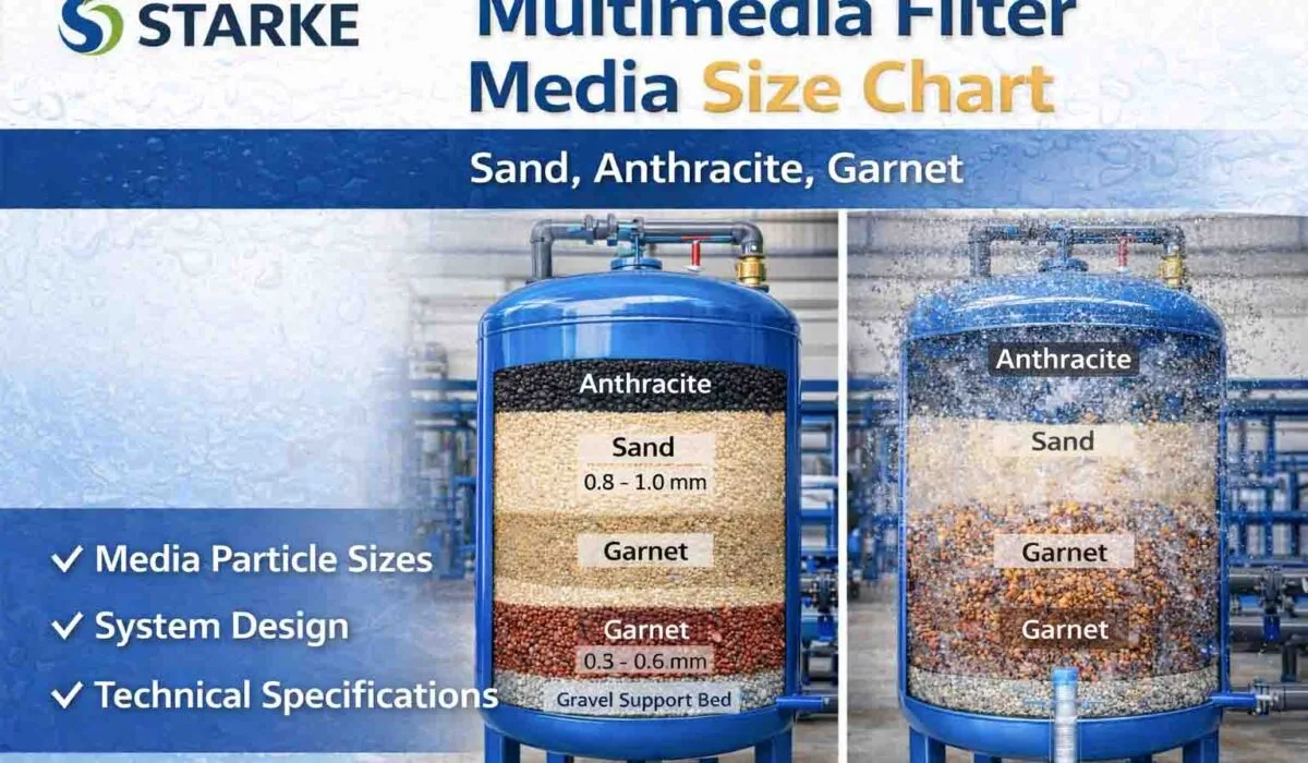
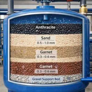
Multimedia filters typically contain three different layers of granular media:
Anthracite filter media (top layer)
Silica sand filter media (middle layer)
Garnet filter media (bottom layer)
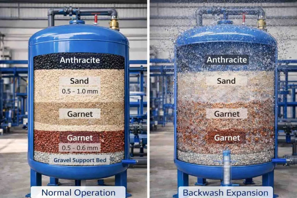
Each layer has a specific particle size and density that allows it to remain separated within the filter bed during operation and backwashing. The larger, lighter particles remain on top, while the smaller, heavier particles settle at the bottom.
A size chart helps engineers select:
Effective particle size (D10)
Uniformity coefficient (UC)
Bed depth
Media layer sequence
Correct sizing ensures the filter captures suspended solids efficiently while maintaining acceptable pressure drop across the filter bed.
Why Multimedia Filter Media Size Charts Are Used
The size of filter media particles directly influences filtration efficiency and hydraulic performance. Without proper grading, a multimedia filter may suffer from problems such as channeling, poor filtration, or excessive pressure drop.
Using a multimedia filter media size chart helps achieve several important objectives.
Improved Filtration Efficiency
Correct particle size distribution ensures contaminants are captured throughout the depth of the filter bed rather than only on the surface.
Higher Solids Loading Capacity
Multimedia filters can hold more suspended solids before backwashing compared to single-media filters.
Reduced Pressure Drop
Proper grading prevents excessive resistance to flow, allowing water to pass through the filter efficiently.
Stable Media Layering
Different densities and particle sizes allow each media layer to remain properly separated during filtration and backwashing.
Consistent Water Quality
Correct sizing ensures turbidity and suspended solids are consistently removed from water.
Because of these benefits, multimedia filtration is widely used in municipal water treatment plants, industrial filtration systems, and RO pretreatment applications.
Technical Specifications for Multimedia Filter Media
A multimedia filter typically uses a combination of three filtration media with carefully controlled particle sizes and densities.
Below is a commonly used multimedia filter media size chart.
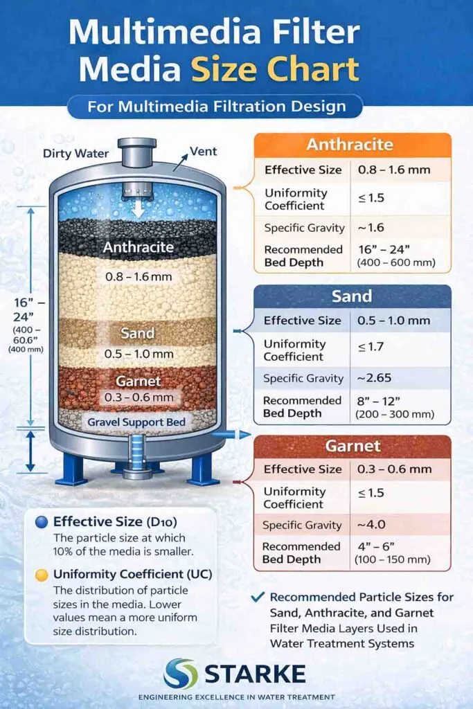
| Media Type | Effective Size | Uniformity Coefficient | Specific Gravity | Typical Bed Depth |
|---|---|---|---|---|
| Anthracite | 0.8 – 1.6 mm | ≤ 1.5 | ~1.6 | 400 – 600 mm |
| Sand | 0.5 – 1.0 mm | ≤ 1.7 | ~2.65 | 200 – 300 mm |
| Garnet | 0.3 – 0.6 mm | ≤ 1.5 | ~4.0 | 100 – 150 mm |
Effective Size (D10)
The effective size represents the particle diameter at which 10 percent of the particles are smaller. It influences filtration fineness and hydraulic resistance.
Uniformity Coefficient
The uniformity coefficient (UC) indicates the distribution of particle sizes in the media. Lower UC values indicate more uniform particles and better filtration performance.
Specific Gravity
Different densities ensure the media layers remain properly arranged in the filter bed during backwashing.
Bed Depth
Adequate bed depth ensures sufficient contact between water and filter media for effective particle removal.
How Multimedia Filter Media Works
Multimedia filters remove suspended particles through several filtration mechanisms.
Mechanical Straining
Larger particles are trapped between filter media grains.
Interception
Particles moving with water flow collide with media particles and attach to their surface.
Sedimentation
Heavier particles settle within the pore spaces of the filter bed.
Depth Filtration
Unlike surface filters, multimedia filters capture particles throughout the entire filter bed depth.
Because of this layered filtration mechanism, multimedia filters can remove a wide range of particle sizes while maintaining low pressure drop.
When the filter becomes loaded with contaminants, it is cleaned through backwashing, where water flows upward through the filter bed to expand the media and remove trapped solids.
Applications of Multimedia Filtration
Multimedia filtration is widely used in many water treatment processes.
Municipal Drinking Water Treatment
Cities use multimedia filters to remove turbidity and suspended solids from surface water sources.
Reverse Osmosis Pretreatment
RO plants rely on multimedia filters to reduce turbidity and silt density index before water reaches membranes.
Industrial Water Treatment
Industries such as power plants, petrochemical plants, and manufacturing facilities use filtration to protect equipment and improve water quality.
Desalination Plants
Pretreatment filtration helps remove suspended solids from seawater before membrane desalination.
Wastewater Reuse
Multimedia filters are used to remove suspended solids in tertiary wastewater treatment processes.
Comparison with Other Filter Media Systems
Several filtration systems are available for water treatment.
Single Media Sand Filters
Sand filters use only one layer of filtration media. While effective, they have lower solids holding capacity compared to multimedia filters.
Cartridge Filters
Cartridge filters provide fine filtration but require frequent replacement and have limited capacity.
Membrane Filtration
Ultrafiltration and microfiltration systems provide higher filtration efficiency but require higher investment and operating costs.
Multimedia filters offer a balance between performance, reliability, and cost, making them one of the most commonly used filtration technologies.
Advantages of Multimedia Filter Media
Using a properly designed multimedia filter provides several advantages.
Higher Filtration Efficiency
Layered media captures particles of different sizes effectively.
Longer Filter Run Time
Multimedia filters allow longer operation between backwash cycles.
Reduced Operating Costs
Lower backwash frequency reduces energy and water consumption.
Improved Downstream Process Protection
Multimedia filtration protects RO membranes and other treatment equipment from particulate fouling.
Greater Solids Holding Capacity
Multimedia filters can hold more contaminants compared to single-media filters.
Common Mistakes in Multimedia Filter Design
Improper design or media selection can reduce filter performance.
Incorrect Media Size Selection
Improper particle size distribution may cause poor filtration efficiency.
Poor Uniformity Coefficient
Wide particle size distribution may lead to channeling within the filter bed.
Incorrect Layer Thickness
Improper bed depth reduces filtration capacity.
Incorrect Backwash Velocity
Inadequate backwashing may not remove trapped contaminants effectively.
Mixing Media with Similar Density
If densities are too similar, media layers may mix during backwash.
Correct design and high-quality filter media are essential for long-term filtration performance.
FAQs
What is the most common multimedia filter configuration?
The most common configuration uses anthracite, sand, and garnet arranged from top to bottom.
Why is anthracite placed on top?
Anthracite has lower density and larger particle size, allowing it to remain on top and capture larger suspended particles.
What turbidity level can multimedia filters remove?
Properly designed multimedia filters can reduce turbidity to below 1 NTU.
What is the typical filtration velocity?
Most multimedia filters operate between 5 and 15 meters per hour.
How often should multimedia filters be backwashed?
Backwash frequency depends on influent turbidity but typically occurs every 24–72 hours.
Conclusion
Multimedia filtration is a highly effective technology for removing suspended solids and turbidity in water treatment systems. By combining layers of anthracite, sand, and garnet with carefully selected particle sizes, multimedia filters provide efficient depth filtration and extended operational cycles.
Using a proper multimedia filter media size chart helps engineers design filtration systems that achieve optimal performance while maintaining stable hydraulic conditions. When correctly designed, multimedia filters improve water quality, protect downstream treatment processes, and reduce operating costs.
Selecting high-quality filtration media with appropriate particle size distribution, uniformity coefficient, and density ensures reliable filtration performance in municipal, industrial, and desalination water treatment plants.